Table of Contents
Technical Installation Requirements
Engineering Standards for Reliable Stainless Steel Piping Systems
Minimum Spacing Requirements
During press connections, minor deformation occurs at pipe joints. Maintaining proper spacing between connections is essential for system integrity.
Basic Handling Principles
| Nominal Diameter(DN) | Minimum Spacing L(mm) |
| 15-25 | 20 |
| 32-50 | 40 |
| 65-100 | 60 |
Elbow Combination Safety Dimensions
| DN | 15 | 20 | 25 | 32 | 40 | 50 | 65 | 80 | 100 |
| 45°L(mm) | 48 | 56 | 65 | 90 | 107 | 118 | 233 | 270 | 320 |
| 90°L(mm) | 54 | 64 | 82 | 104 | 126 | 140 | 263 | 305 | 355 |
Pipe Supports and Hangers
Stainless Steel Brackets (with nuts)
Stainless Steel Rod-type Pipe Clamps
Stainless Steel Single Clamps
Gas Pipeline Compensation
Expansion Calculation
ΔL = α * L * ΔT Where: α - Linear expansion coefficient (stainless steel: 0.0173 mm/m·°C) L - Pipe length between fixed supports (meters) ΔT - Temperature differential (°C)
Compensation Methods
Natural Compensation: Free arm length calculation
Type II Compensation: U-shaped expansion loops
Z-Type Compensation: Offset expansion configuration
Cross Compensation: Multi-directional expansion handling
Ring Compensation: Circular expansion loops
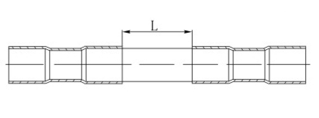
Bellows Expansion Joints: For DN32 and larger pipes
Application Guidelines
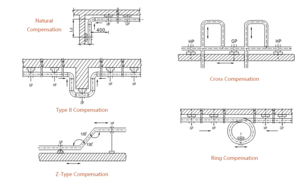
Type II or bellows compensators preferred for gas mains and high-rise buildings
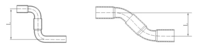
Natural, Type II, and Z-type compensation can be installed horizontally or vertically
Bellows expansion joints recommended for DN32 and larger pipelines
Pipeline Installation Specifications
Penetration Requirements
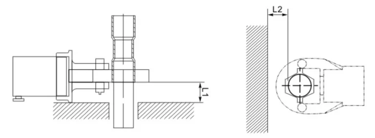
When gas pipelines pass through trenches, building foundations, walls, and floors:
Must be installed within sleeves/casings, preferably coaxial
No connection joints permitted within sleeve sections
Wall, floor, and embedded sections should have protective coating or plastic coating
Annulus between pipe and sleeve filled with flexible, corrosion-resistant waterproof material
Space between sleeve and building structure filled with waterproof material
Minimum Sleeve Diameter Requirements
| Nominal Diameter(DN) | 15 | 20 | 25 | 32 | 40 | 50 | 65 | 80 | 100 |
| L1(mm) | 48 | 56 | 65 | 90 | 107 | 118 | 233 | 270 | 320 |
| L2(mm) | 54 | 64 | 82 | 104 | 126 | 140 | 263 | 305 | 355 |
Important Notice
These technical requirements are minimum standards. Always consult local building codes, project specifications, and engineering requirements. Nonleak recommends professional installation by certified technicians for all piping systems.