Table of Contents
Technical Installation Requirements
Engineering Standards for Reliable Stainless Steel Piping Systems
Use this technical documentation as a practical stainless steel pipe installation reference for Nonleak press-fit piping systems. It helps installers understand coupling spacing, elbow dimensions, pipe supports, thermal compensation and sleeve penetration requirements. For a complete system, please use compatible Nonleak stainless steel pipes, stainless steel pipe fittings and pipeline accessories according to project specifications.
Minimum Spacing Requirements for Stainless Steel Pipe Installation
During press connections, minor deformation occurs at pipe joints. For stainless steel pipe installation, proper spacing between couplings and elbows helps prevent interference, protect sealing areas and support long-term joint integrity.
Basic Handling Principles
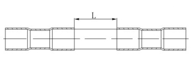
| Nominal Diameter(DN) | Minimum Spacing L(mm) |
| 15-25 | 20 |
| 32-50 | 40 |
| 65-100 | 60 |
Elbow Combination Safety Dimensions
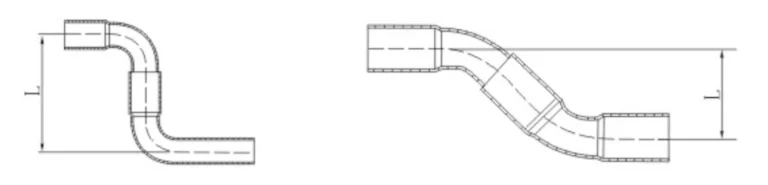
| DN | 15 | 20 | 25 | 32 | 40 | 50 | 65 | 80 | 100 |
| 45°L(mm) | 48 | 56 | 65 | 90 | 107 | 118 | 233 | 270 | 320 |
| 90°L(mm) | 54 | 64 | 82 | 104 | 126 | 140 | 263 | 305 | 355 |
Pipe Supports and Hangers
Pipe supports and hangers should match pipe diameter, route direction, load conditions and site environment. Suitable brackets, rod-type clamps and single clamps help keep stainless steel pipelines stable and reduce vibration during operation.
Stainless Steel Brackets (with nuts)
Stainless Steel Rod-type Pipe Clamps
Stainless Steel Single Clamps
Gas Pipeline Compensation
Gas pipeline compensation helps control movement caused by temperature changes. The following calculation and methods are used to evaluate thermal expansion and select a suitable compensation layout for stainless steel piping systems.
Expansion Calculation
ΔL = α * L * ΔT
Where:
α - Linear expansion coefficient (stainless steel: 0.0173 mm/m·°C)
L - Pipe length between fixed supports (meters)
ΔT - Temperature differential (°C)
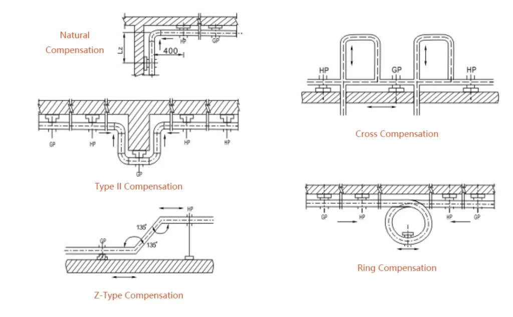
Compensation Methods
Natural Compensation: Free arm length calculation
Type II Compensation: U-shaped expansion loops
Z-Type Compensation: Offset expansion configuration
Cross Compensation: Multi-directional expansion handling
Ring Compensation: Circular expansion loops
Bellows Expansion Joints: For DN32 and larger pipes
Application Guidelines
Type II or bellows compensators preferred for gas mains and high-rise buildings
Natural, Type II, and Z-type compensation can be installed horizontally or vertically
Bellows expansion joints recommended for DN32 and larger pipelines
Pipeline Penetration and Sleeve Installation Specifications
This section covers stainless steel pipe installation through trenches, foundations, walls and floors. Sleeves or casings should protect the pipe, avoid hidden joints and allow proper waterproof sealing around the penetration.
Penetration Requirements
When gas pipelines pass through trenches, building foundations, walls, and floors:
Must be installed within sleeves/casings, preferably coaxial
No connection joints permitted within sleeve sections
Wall, floor, and embedded sections should have protective coating or plastic coating
Annulus between pipe and sleeve filled with flexible, corrosion-resistant waterproof material
Space between sleeve and building structure filled with waterproof material
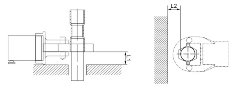
Minimum Sleeve Diameter Requirements
| Nominal Diameter(DN) | 15 | 20 | 25 | 32 | 40 | 50 | 65 | 80 | 100 |
| L1(mm) | 48 | 56 | 65 | 90 | 107 | 118 | 233 | 270 | 320 |
| L2(mm) | 54 | 64 | 82 | 104 | 126 | 140 | 263 | 305 | 355 |
Before final acceptance, installers should check sleeve clearance, sealing details, visible joints and pipe protection. For pressure testing and site inspection requirements, refer to Testing & Acceptance. For press tools and regular equipment checks, refer to Tool Maintenance.
Important Notice
These technical requirements are minimum standards for stainless steel pipe installation. Always follow local building codes, approved project drawings, engineering specifications and applicable piping standards before installation.
For project support, review our Testing & Acceptance page, Tool Maintenance page, stainless steel pipes, stainless steel pipe fittings or contact Nonleak before installation.
For general reference, installers may also review ASME B31.9 Building Services Piping, ASTM A312 stainless steel pipe specification and ASTM A403 stainless steel fittings specification.
Nonleak recommends professional installation by certified technicians for all piping systems. If you need product selection or project support, please contact Nonleak before installation.