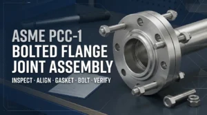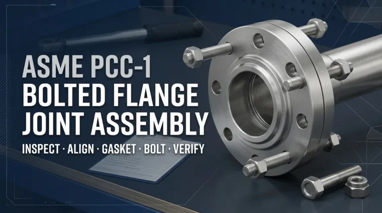
ASME PCC-1 provides guidelines for the assembly of pressure-boundary bolted flange joints.
It addresses practical areas such as joint preparation, flange and fastener inspection, alignment, gasket installation, bolting, controlled tightening, quality assurance, assembly records and troubleshooting.
However, PCC-1 should not be treated as a replacement for the flange standard, material specification, piping code or approved project procedure.
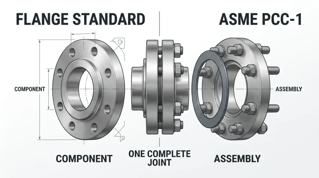
A useful way to understand its role is:
the product standards define the components, while PCC-1 helps address how the bolted flange joint is prepared and assembled.
This guide explains what ASME PCC-1 covers, how it relates to standards such as ASME B16.5, and what engineers, inspectors and project teams should verify before closing a flanged joint.
What Is ASME PCC-1?
ASME PCC-1 is titled Pressure Boundary Bolted Flange Joint Assembly.
The current ASME edition is PCC-1–2022.
The document provides guidance for developing effective assembly procedures for pressure-boundary bolted flange joints within its defined scope.
Its role extends beyond simply tightening bolts.
Bolted flange joint integrity depends on the interaction of several components and activities:
- flanges;
- gaskets;
- studs or bolts;
- nuts and washers where specified;
- lubrication;
- flange-face condition;
- alignment;
- assembly bolt load;
- tightening method;
- inspection;
- documentation.
PCC-1 brings these factors into a structured bolted-joint assembly framework.
What Does ASME PCC-1 Apply To?
ASME describes PCC-1 as guidance for defined pressure-boundary bolted flange joints using ring-type gaskets located within the circle enclosed by the bolt holes and without contact outside that circle.
This scope detail matters.
PCC-1 should not automatically be applied to every mechanical flange, clamp, hygienic connection or specialty joint simply because bolts are present.
The project team should confirm:
- whether PCC-1 applies to the specific joint;
- which edition is invoked by the project;
- which portions are incorporated into the approved assembly procedure;
- what additional piping-code, owner or equipment requirements apply.
ASME PCC-1 vs ASME B16.5
ASME PCC-1 and ASME B16.5 perform different roles.
| Document | Primary Role | Typical Project Question |
|---|---|---|
| ASME B16.5 | Pipe flange and flanged-fitting requirements within its applicable scope | What flange size, class, dimensions, material and facing requirements apply? |
| ASME PCC-1 | Pressure-boundary bolted flange joint assembly guidance | How should the joint be inspected, prepared, aligned, assembled and documented? |
| Material Specifications | Component material and product requirements | Which flange, bolting and other material specifications are required? |
| Piping Code | System design, fabrication, examination and testing framework | What requirements apply to the complete piping system? |
| Project Specification | Owner / engineer requirements | What procedure, inspection, records and acceptance criteria are required for this project? |
For this reason, specifying “ASME B16.5 flange” alone does not create a complete bolted flange joint assembly procedure.
Likewise, citing ASME PCC-1 does not by itself define the flange material, pressure class, gasket or bolting specification.
Main Components of a Bolted Flange Joint
Before discussing tightening, it helps to treat the assembly as a system.
Flanges
The mating flanges provide the structural and sealing interfaces of the joint.
Their type, material, pressure class, facing, surface condition and geometry must be compatible with the approved piping design.
Gasket
The gasket creates the sealing element between the mating flange faces.
Its material, construction, dimensions and service suitability should follow the approved specification.
A gasket should not be selected only by nominal flange size.
Bolting
Studs or bolts and nuts create the clamping force required by the joint design and gasket system.
Material, dimensions, thread condition, lubrication and tightening method can all influence the relationship between applied tool input and resulting bolt load.
Lubrication
Lubrication affects friction in threaded and nut-bearing surfaces.
Therefore, torque values should not be separated from the lubricant and friction assumptions used to develop the approved tightening procedure.
Pre-Assembly Inspection Before Closing the Joint
A reliable bolted flange joint begins before the first tightening pass.
A practical pre-assembly review may include:
- confirming the correct flanges and facing type;
- checking flange sealing surfaces for condition and damage;
- confirming the correct new gasket;
- checking gasket condition and dimensions;
- checking bolt, stud and nut identification;
- checking threads for damage or contamination;
- confirming the specified lubricant;
- checking flange alignment;
- checking that fasteners can be installed without forcing the joint into alignment;
- confirming required tools and calibrated equipment;
- confirming the approved assembly procedure;
- confirming required inspection and documentation.
The exact acceptance limits should come from the applicable controlled standards and project procedure rather than a generic online checklist.
Why Flange Alignment Matters
Flange alignment affects how load is transferred through the joint.
A bolting procedure should not be used as a substitute for correcting unacceptable piping or flange misalignment.
If bolts have to pull severely misaligned flanges together, the resulting joint may experience uneven gasket loading or unintended piping and equipment loads.
Project teams should consider:
- centerline alignment;
- flange-face parallelism;
- rotational bolt-hole alignment;
- joint gap;
- loads imposed on connected equipment;
- the approved alignment method.
Where alignment requires excessive force, the condition should be reviewed under the approved engineering procedure rather than solved by simply applying more bolt torque.
Gasket Inspection and Installation
Gasket installation is another area where the complete joint specification matters.
Before installation, verify:
- correct gasket type;
- correct material;
- correct nominal size and class compatibility;
- correct dimensions;
- clean condition;
- absence of unacceptable handling damage;
- correct position between the flange faces.
A gasket that is incorrectly selected, damaged or poorly positioned cannot be corrected simply by increasing bolt torque.
The flange surface condition and gasket specification should therefore be checked before tightening begins.
Bolts, Studs, Nuts and Lubrication
The fastener system should be treated as part of the engineered joint.
Typical checks include:
- bolt or stud specification;
- nut specification;
- diameter and length;
- thread condition;
- material identification;
- nut engagement;
- bearing surfaces;
- lubricant type;
- project restrictions on coatings or anti-seize compounds.
Changing lubricant, surface coating or bolting condition can change the friction behavior of the assembly.
This is one reason a torque value copied from a generic chart should not automatically be used as a project tightening instruction.
Torque Is Not the Same as Bolt Load
This is one of the most important concepts in bolted flange assembly.
Torque is an assembly input. Bolt load is the mechanical result the procedure is trying to achieve.
The relationship between the two can be influenced by:
- bolt diameter;
- bolt and nut material;
- thread condition;
- lubrication;
- coating;
- friction;
- flange geometry;
- gasket behavior;
- tightening equipment;
- the selected assembly method.
Therefore, there is no technically responsible universal “ASME PCC-1 torque value” that can be applied to every flange of the same nominal size.
Does ASME PCC-1 Provide a Bolt Tightening Sequence?
PCC-1 addresses bolted-joint assembly methods and tightening practices, including approaches intended to develop suitable and reasonably uniform joint loading.
However, the field procedure should be based on the applicable PCC-1 guidance, joint design, gasket, bolting, project requirements and approved assembly procedure.
A generic sequence copied from the internet should not replace the controlled procedure.
This is particularly important because the appropriate tightening method can vary with:
- number of bolts;
- flange configuration;
- gasket type;
- target bolt load;
- tooling;
- joint criticality;
- project procedure.
Torque Tightening vs Hydraulic Tensioning
Torque wrenches are widely used for flange assembly, but torque is not the only method available for applying fastener load.
Depending on the project and joint, assembly methods may include:
- manual torque tightening;
- hydraulic torque tools;
- hydraulic bolt tensioning;
- other approved controlled-load methods.
The choice depends on joint design, bolt size, access, required load control, equipment availability and project procedures.
The key objective is not to select the most powerful tool, but to achieve the approved assembly condition safely and consistently.
Quality Assurance During Flange Assembly
Bolted-joint QA should not begin only after a leak appears.
Depending on project requirements, quality control may include:
- component identification;
- flange-face inspection;
- gasket verification;
- fastener inspection;
- alignment checks;
- tool calibration verification;
- lubricant confirmation;
- confirmation of the approved tightening procedure;
- in-process observation;
- final joint inspection;
- joint assembly records.
For a broader overview of Nonleak manufacturing and inspection practices, see our quality control and testing page.
What Should Be Recorded for a Critical Flange Joint?
The exact record format depends on the owner and project, but a bolted-joint record may need to identify information such as:
- joint or line identification;
- flange size and class;
- gasket type;
- bolting specification;
- lubricant;
- assembly method;
- approved procedure reference;
- tool identification or calibration status;
- assembler / inspector identification where required;
- inspection status;
- completion date;
- nonconformances or corrective actions.
This creates traceability between the physical joint and the project’s assembly and QA documentation.
ASME PCC-1 and Bolting Personnel Training
PCC-1 also addresses the competency and training of personnel involved in bolted flange joint assembly.
This is important because correct components and a correct engineering specification still depend on controlled field execution.
Training topics can include:
- identifying joint components;
- pre-assembly inspection;
- gasket handling;
- alignment;
- bolting and lubrication;
- tightening equipment;
- assembly methods;
- quality assurance;
- documentation;
- troubleshooting.
The project should define what training, qualification or competency evidence is required for the personnel performing and inspecting the work.
What ASME PCC-1 Does Not Replace
PCC-1 should be integrated into the complete piping and project documentation framework.
It does not replace:
- the piping design code;
- flange product standards;
- material specifications;
- approved gasket specifications;
- bolting specifications;
- equipment manufacturer requirements;
- project engineering calculations;
- owner specifications;
- approved installation and inspection procedures.
This distinction prevents a common documentation mistake: treating one standard number as though it defines the complete flange joint.
ASME PCC-1 vs a Flange Specification
| Question | Usually Controlled By |
|---|---|
| What flange type is required? | Project design + flange standard |
| What pressure class is required? | Engineering design + applicable flange standard |
| What flange material is required? | Material specification + project requirements |
| What gasket is required? | Project gasket specification / approved joint design |
| What bolting material is required? | Project / material specification |
| How should the joint be prepared and assembled? | Approved bolted-joint procedure using applicable PCC-1 guidance |
| What torque or bolt load should be used? | Approved joint-specific assembly procedure |
| What inspection and records are required? | Project QA/QC plan + approved procedure |
Bolted Flange Joint Pre-Closure Checklist
Before a flange joint is closed, the project team can use a checklist such as the following as a planning framework:
| Check | Confirm |
|---|---|
| Joint Identification | Correct line / equipment / joint ID |
| Flanges | Correct type, size, class, material and facing |
| Flange Faces | Clean and acceptable under the project procedure |
| Alignment | Within approved project / PCC-1 based requirements |
| Gasket | Correct type, material, size and undamaged condition |
| Bolting | Correct material, size, length and condition |
| Lubrication | Correct product and application |
| Tools | Correct equipment and valid calibration where required |
| Procedure | Current approved assembly instruction available |
| Inspection | Required hold / witness points identified |
| Records | Required assembly documentation prepared |
This is a project-planning checklist, not a substitute for the controlled PCC-1 text or the project-specific assembly procedure.
Preparing Flange and Piping Documentation for a Project?
Send the applicable piping specification, flange requirements, material requirements and required inspection documentation.
Nonleak can help review the piping-component and technical-document scope before quotation. Final flange-joint design and field assembly procedures remain subject to the approved project engineering documents.
ASME PCC-1 FAQ
What is ASME PCC-1?
ASME PCC-1 provides guidelines for pressure-boundary bolted flange joint assembly within its defined scope. It covers practical areas including preparation, inspection, alignment, gaskets, bolting, tightening, quality assurance and troubleshooting.
What is the current edition of ASME PCC-1?
ASME currently lists PCC-1–2022 as the current edition of Pressure Boundary Bolted Flange Joint Assembly. Projects should still confirm the edition explicitly invoked by their contracts and specifications.
Is ASME PCC-1 the same as ASME B16.5?
No. ASME B16.5 is a flange and flanged-fitting product standard within its scope. PCC-1 addresses bolted flange joint assembly guidance. They perform different but complementary roles.
Does ASME PCC-1 give flange torque values?
PCC-1 contains bolted-joint assembly guidance, but a field torque value should not be selected from nominal flange size alone. The approved value or target load depends on the complete joint, including gasket, bolting, flange, lubrication, service and project procedure.
Does PCC-1 require a star tightening pattern?
PCC-1 addresses tightening procedures and assembly patterns, but the applicable pattern and load steps should come from the current controlled guidance and approved project procedure rather than a generic online sequence.
Why is lubrication important in flange bolting?
Lubrication affects friction at threads and bearing surfaces, which affects the relationship between applied torque and resulting bolt load. The approved torque procedure should therefore identify its lubrication assumptions.
Can bolts be used to pull misaligned flanges together?
Bolting should not be treated as a general substitute for correcting unacceptable flange or piping alignment. Conditions outside the approved alignment criteria should be reviewed before gasket installation and final tightening.
What records are needed for a bolted flange joint?
Project requirements may call for joint identification, flange and gasket data, bolting and lubrication information, assembly procedure, tool or calibration information, assembler or inspector identification, inspection status and completion records.
From Flange Selection to Joint Assembly
A reliable flanged piping connection requires more than selecting the correct nominal flange.
The project also has to align:
- flange standard and material;
- gasket selection;
- bolting;
- joint geometry;
- assembly procedure;
- inspection;
- testing;
- documentation.
For lap-joint assemblies specifically, see our stub end flange guide to understand how the stub end and loose backing flange work together before assembly.
Preparing a Piping or Flange RFQ?
Send the flange requirements, material specifications, piping standard, quantities and required QA / documentation scope.
Technical Note: This article is a general technical and procurement guide. It does not reproduce or replace the controlled text of ASME PCC-1, ASME B16.5, the governing piping code, approved joint calculations, manufacturer instructions or project-specific assembly procedures.