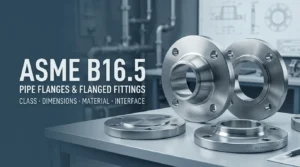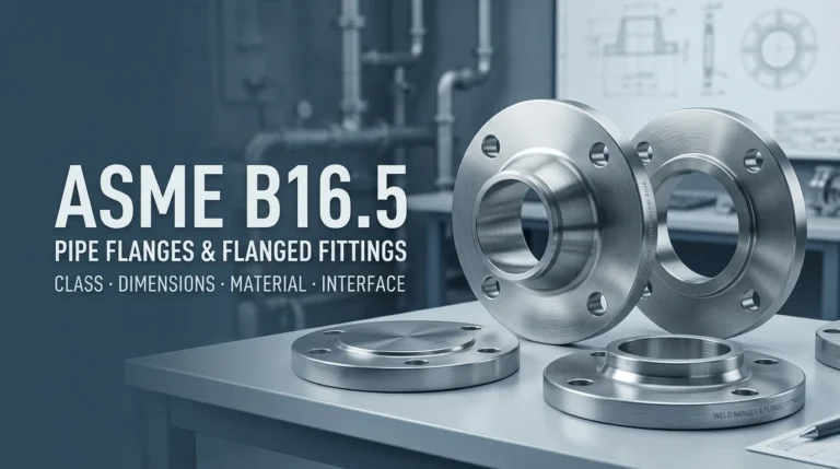
ASME B16.5 is one of the most widely referenced standards for pipe flanges and flanged fittings in pressure piping. It is often associated with familiar terms such as Class 150, Class 300, raised-face flanges and flange dimensions, but the standard covers more than a dimensional table. It provides a framework for pressure-temperature ratings, materials, dimensions, tolerances, marking, testing and related flange-joint requirements within its defined scope.
For engineers and buyers, the important question is not simply, “Is this an ASME B16.5 flange?” A complete specification normally also needs the correct flange type, nominal pipe size, rating class, material, facing, mating interface and project requirements. B16.5 should therefore be read as one part of a complete piping specification rather than as a substitute for material specifications, piping codes or approved joint-assembly procedures.
Current edition note: At the time of writing, ASME lists ASME B16.5-2025 as the current edition. Projects should always use the edition required by the contract, governing code or approved project documents.
What Is ASME B16.5?
ASME B16.5 is the ASME standard titled Pipe Flanges and Flanged Fittings: NPS 1/2 through NPS 24, Metric/Inch Standard. Its scope includes pressure-temperature ratings, materials, dimensions, tolerances, marking, testing and methods of designating openings for pipe flanges and flanged fittings.
The standard covers defined combinations of nominal pipe size and rating class. It is primarily associated with cast or forged flanges and flanged fittings, while blind flanges and certain reducing flanges may also be made from plate materials within the conditions permitted by the standard.
ASME B16.5 also contains requirements and recommendations related to flange bolting, gaskets and flange joints. However, that does not make B16.5 a complete field assembly procedure. Product standardization, material selection, piping design and joint assembly remain separate parts of the overall engineering framework.
For a broader explanation of how different standards work together in a piping specification, see our ASTM vs ASME standards guide.
What Does ASME B16.5 Cover?
From a procurement perspective, B16.5 helps define the standardized interface that allows a flange to be specified and checked consistently. Important areas include the following.
| Area | What It Controls or Helps Define |
|---|---|
| Pressure-temperature ratings | The rating framework associated with material groups, rating classes and temperature conditions. |
| Materials | Material requirements and the material-group framework used with the standard; separate material/product specifications may also be required. |
| Dimensions | Standardized flange and flanged-fitting geometry, including mating and bolting interfaces within the applicable scope. |
| Tolerances | Permitted dimensional variation for standardized components. |
| Marking | Identification requirements used to communicate required product information. |
| Testing | Testing requirements applicable to products within the scope of the standard. |
| Bolting, gaskets and joints | Requirements and recommendations that support a compatible flanged-joint interface, without replacing a controlled joint-assembly procedure. |
This is why an RFQ that states only “ASME B16.5 flange” is usually incomplete. The standard gives the framework, but the purchase order still has to identify the actual component required.
What Size and Pressure-Class Range Does ASME B16.5 Cover?
The size range depends on the rating class. For flanges, ASME B16.5 covers Classes 150, 300, 400, 600, 900 and 1500 from NPS 1/2 through NPS 24. Class 2500 flanges are covered from NPS 1/2 through NPS 12.
| Flange Rating Class | ASME B16.5 Flange Size Scope |
|---|---|
| 150, 300, 400, 600, 900, 1500 | NPS 1/2 through NPS 24 |
| 2500 | NPS 1/2 through NPS 12 |
The scope for flanged fittings has additional details, so buyers should not assume that every flange and every flanged fitting has the same class-and-size coverage. When a project falls outside the B16.5 flange size range, another standard may apply.
What Do ASME B16.5 Pressure Classes Mean?
ASME B16.5 uses rating class designations such as Class 150, 300, 400, 600, 900, 1500 and 2500. These class numbers are standardized rating designations. They should not be treated as simple pressure values.
The actual pressure-temperature rating depends on factors defined by the standard, including the material group and temperature. This matters because a flange that is acceptable at one temperature cannot automatically be assumed to have the same allowable pressure at a substantially different temperature.
For practical procurement, the correct sequence is therefore:
design conditions → applicable piping code/project specification → material → required pressure-temperature rating → flange class → complete flange specification.
Choosing a class number first and trying to justify the design afterward reverses that engineering logic.
Does Class 150 Mean 150 PSI?
No. Class 150 does not mean that every Class 150 flange has a universal pressure limit of 150 psi.
The class number is a rating designation. Actual allowable pressure is determined from the applicable pressure-temperature rating for the relevant material group and metal temperature, together with the governing piping code and project requirements.
The same principle applies to the other class numbers. Class 300 should not be read as a universal 300 psi rating, and Class 600 should not be read as a universal 600 psi rating. A generic “class-to-psi” conversion table can therefore be misleading if it ignores material and temperature.
For design or acceptance work, use the controlled edition of ASME B16.5 required by the project rather than an uncontrolled online pressure chart.
What Dimensions Are Defined by ASME B16.5?
B16.5 standardizes the geometry needed for compatible flange and flanged-fitting interfaces. Depending on the component type, relevant dimensional characteristics can include the overall flange envelope, flange thickness, bolt-hole arrangement, bolt-circle geometry, bore or hub geometry, facing details and other connection dimensions.
| RFQ or Drawing Term | Why It Matters |
|---|---|
| NPS / DN | Identifies the nominal connection size and the dimensional family to be checked. |
| Flange outside diameter | Defines part of the overall component envelope. |
| Flange thickness | Forms part of the standardized component geometry. |
| Bolt circle | Controls the bolting layout and mating compatibility. |
| Bolt-hole quantity and diameter | Must match the intended mating flange and bolting arrangement. |
| Bore / hub geometry | Important for the pipe-to-flange interface, depending on flange type. |
| Facing | Defines the gasket-contact and sealing interface. |
This article intentionally does not reproduce the complete copyrighted dimensional tables from ASME B16.5. For fabrication, dimensional verification or final procurement acceptance, use the applicable controlled standard and approved project drawings.
Common ASME B16.5 Flange Types
Different flange forms solve different connection and fabrication requirements. Common flange types encountered in B16.5-based piping specifications include welding neck, slip-on, threaded, socket-weld, lap-joint and blind flanges. The correct choice depends on the piping design, material, connection method, service conditions, inspection requirements and project specification.
Welding Neck Flange
A welding neck flange uses a tapered hub and a butt-welded connection to the pipe. Its selection should be coordinated with the pipe outside diameter, wall thickness or bore requirements, weld preparation and the applicable welding procedure.
Slip-On Flange
A slip-on flange fits over the pipe and uses welds to connect the flange and pipe. It should not be treated as interchangeable with a welding neck flange simply because the nominal size and class are the same.
Threaded Flange
A threaded flange provides a threaded connection rather than a butt-welded pipe connection. Suitability depends on the service, material, thread requirements and governing project rules.
Socket-Weld Flange
A socket-weld flange uses a socket-type pipe interface. As with other socket-weld components, the flange type alone does not establish a complete welding or installation requirement.
Lap-Joint Flange
A lap-joint flange is used with a compatible stub-end arrangement. The loose flange provides the bolting interface while the stub end forms the process-side connection. For a detailed explanation of the two-component relationship, see our stub end and lap joint flange guide.
Blind Flange
A blind flange closes a flanged opening. Its geometry and loading differ from a flange with a through bore, so it should be specified as the correct component type rather than treated as a generic flange plate.
Not every flange type, material, size and class combination is automatically available or appropriate. Final selection should be checked against the applicable standard edition, material specification, piping code and project documents.
Raised Face, Flat Face and RTJ: Why Flange Facing Matters
The flange facing is part of the sealing interface. Common terminology includes raised face (RF), flat face (FF) and ring-type joint (RTJ), but the correct facing cannot be chosen in isolation.
Facing selection should be coordinated with the mating flange, gasket type, flange class, material, service conditions and approved project specification. Two flanges with the same NPS and class may still be incompatible if their required sealing interfaces do not match.
This is also why an RFQ such as “4-inch Class 300 flange” remains incomplete. At minimum, the buyer still needs to confirm the flange type, material, facing and other project-specific requirements.
Does ASME B16.5 Specify Flange Materials?
B16.5 includes material requirements and a material framework used with its pressure-temperature ratings. However, a complete purchase specification may also need a separate material or product specification.
For example, ASTM A182/A182M is a material/product specification that covers forged or rolled alloy and stainless steel piping components, including flanges, fittings, valves and similar parts for its defined service scope. B16.5 and a specification such as ASTM A182 therefore perform different but complementary functions.
| Document | Typical Responsibility in a Flange Specification |
|---|---|
| ASME B16.5 | Flange/flanged-fitting rating, dimensional, tolerance, marking, testing and interface framework within its scope. |
| Material or product specification | Defines the ordered material grade and the applicable material/product requirements. |
| Piping code | Provides the system-level design, fabrication, examination and testing framework. |
| Project specification / datasheet | Defines the project-specific material, class, facing, inspection, documentation and acceptance requirements. |
A standard number should therefore never be used as a shortcut for a complete material description.
ASME B16.5 vs ASME B16.47
The simplest distinction is size scope.
ASME B16.5 covers pipe flanges within its defined ranges up to NPS 24, with Class 2500 flange coverage ending at NPS 12. ASME B16.47 is the large-diameter steel flange standard covering NPS 26 through NPS 60.
| Standard | Primary Flange Size Scope | Role |
|---|---|---|
| ASME B16.5 | NPS 1/2 through NPS 24 for Classes 150–1500; Class 2500 through NPS 12 | Pipe flanges and flanged fittings within the B16.5 scope. |
| ASME B16.47 | NPS 26 through NPS 60 | Large-diameter steel flanges within the B16.47 scope. |
B16.47 should not be treated merely as “the next size table” after B16.5. It has its own scope and requirements, including defined rating classes and large-diameter flange configurations. The project specification should identify the correct governing standard rather than relying only on nominal diameter.
ASME B16.5 vs ASME PCC-1
B16.5 and PCC-1 are related to the same flanged connection, but they answer different questions.
| Question | ASME B16.5 | ASME PCC-1 |
|---|---|---|
| What is the standardized flange/component interface? | Primary role | Not the main role |
| What class, dimensional and product requirements apply? | Primary role within B16.5 scope | Does not replace the product standard |
| How should a pressure-boundary bolted flange joint be prepared and assembled? | Contains related joint requirements/recommendations but is not the complete assembly framework | Primary assembly-guidance role within PCC-1 scope |
| Inspection, alignment, gasket, bolting and controlled assembly practice | Interface requirements are relevant | Detailed joint-assembly focus |
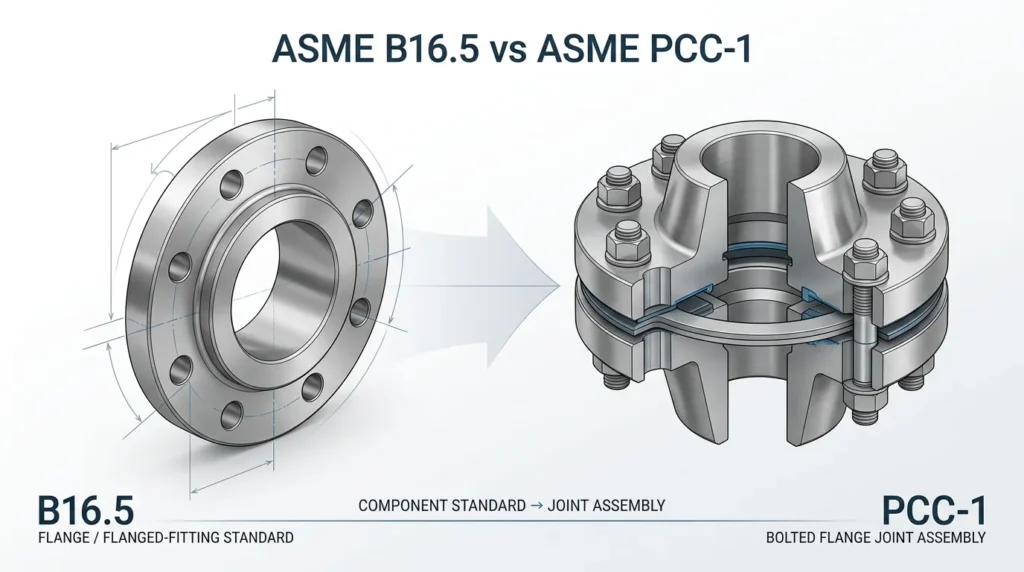
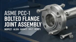
In practical terms, B16.5 helps define the standardized components and interface, while PCC-1 helps address how the pressure-boundary bolted flange joint is prepared and assembled within its scope.
For the assembly side of the subject, see our ASME PCC-1 flange joint assembly guide.
What Should a Buyer Specify in an ASME B16.5 Flange RFQ?
A good RFQ should identify enough information for the supplier to determine exactly which flange is required and which documents must be supplied. A practical review should normally address the following fields.
| RFQ Field | Example of What to Confirm |
|---|---|
| Flange type | Welding neck, slip-on, threaded, socket-weld, lap-joint, blind or other applicable type. |
| Nominal size | NPS / DN as required by the project. |
| Rating class | Required ASME class based on the approved design and material/temperature rating review. |
| Material | Required material/product specification and grade. |
| Facing | RF, FF, RTJ or other approved interface as applicable. |
| Pipe / bore interface | Pipe OD, wall/schedule or bore details needed for the selected flange type. |
| Mating component | Matching flange, valve, equipment nozzle, stub end or other connection interface. |
| Applicable standards | Required ASME B16.5 edition plus material, piping-code and project requirements. |
| Inspection / testing | Project-specific inspection, testing or witness requirements where applicable. |
| Documentation | MTRs, certificates, inspection records, drawings or other approved document requirements. |
| Quantity | Required quantity by size, type, class, material and facing. |
Need Help Reviewing a Flange Specification?
If your project is still defining the flange interface, send the available flange type, size, class, material, facing, mating component, design conditions, applicable standards and drawings. We can help review the product specification and documentation requirements against the available project information.
Common ASME B16.5 Specification Mistakes
1. Treating the Class Number as a PSI Value
Class 150 is not a universal 150 psi pressure limit. Pressure-temperature ratings must be checked for the applicable material group and temperature.
2. Ordering by Size and Class Only
“NPS 4 Class 300” does not fully define a flange. Flange type, material, facing, pipe/bore interface and project requirements still need to be confirmed.
3. Treating B16.5 as the Material Specification
B16.5 includes materials requirements, but the ordered component may also require a separate material/product specification and grade. The standard number alone is not a complete material description.
4. Using B16.5 Outside Its Size Scope
Large-diameter applications may fall under ASME B16.47 or another project-specified standard. Do not extend a B16.5 table beyond its defined range.
5. Assuming Matching NPS and Class Guarantee a Complete Joint Match
Facing, gasket interface, bore, flange type, material, bolting and mating-component requirements still have to be compatible.
6. Treating B16.5 as the Flange Assembly Procedure
B16.5 standardizes the product and interface and includes joint-related requirements, but controlled assembly practice is a separate subject. ASME PCC-1 provides guidance for pressure-boundary bolted flange joint assembly within its scope.
7. Copying an Online Dimension or Pressure Table Without Checking the Edition
Search results can be useful for orientation, but fabrication and acceptance should use the controlled edition required by the project. Edition, material group, units and component type must all be verified before a table is used for engineering or procurement.
ASME B16.5 FAQ
What is the current edition of ASME B16.5?
At the time of writing, ASME lists ASME B16.5-2025 as the current edition. A project may still contractually require another edition, so always follow the governing code, contract and approved project documents.
What sizes does ASME B16.5 cover?
For flanges, Classes 150, 300, 400, 600, 900 and 1500 cover NPS 1/2 through NPS 24. Class 2500 flange coverage is NPS 1/2 through NPS 12. Flanged-fitting scope has additional details that should be checked separately.
Does ASME B16.5 include Class 2500?
Yes. ASME B16.5 includes Class 2500 flanges from NPS 1/2 through NPS 12 within its defined scope.
Is ANSI B16.5 the same as ASME B16.5?
“ANSI B16.5” remains common legacy terminology in drawings, RFQs and industry conversations. The B16 flange standard has a long standards-development history, and the current standard is published by ASME as ASME B16.5. For a new purchase order, use the exact designation and edition required by the project rather than relying on an informal legacy reference.
Does Class 150 mean 150 psi?
No. The class number is a rating designation, not a universal pressure value. The applicable pressure-temperature rating depends on material group and temperature, together with the governing design requirements.
What is the difference between ASME B16.5 and B16.47?
B16.5 covers flanges within its defined ranges up to NPS 24, while B16.47 covers large-diameter steel flanges from NPS 26 through NPS 60.
What is the difference between ASME B16.5 and ASME PCC-1?
B16.5 primarily standardizes flange and flanged-fitting product/interface requirements within its scope. PCC-1 provides guidance for preparing and assembling pressure-boundary bolted flange joints within its scope. They are complementary rather than interchangeable.
Does ASME B16.5 guarantee that two flanges will work together?
Not by the standard designation alone. The project must still confirm size, class, facing, material, bore/interface, gasket, bolting and mating-component compatibility.
From Flange Standard to Complete Joint Review
ASME B16.5 is a critical starting point for standardized pipe flange and flanged-fitting requirements, but a reliable piping specification is built from several coordinated documents. The flange standard, material specification, piping code, gasket and bolting requirements, approved project drawings and assembly procedure all have distinct roles.
For procurement teams, the most useful approach is to define the complete connection rather than sending a standard number alone. Confirm the component type and interface first, then verify the material, rating class, facing, mating component, inspection and documentation requirements.
Nonleak currently uses ASME B16.5 content as technical and procurement guidance. Product availability, material, class, size range and compliance documentation must be confirmed against the actual offered product and project requirements before quotation or approval.
Related resources include our stub end flange guide, ASME PCC-1 bolted flange joint assembly guide, quality control and inspection and technical documentation.
Preparing a Piping or Flanged-Connection RFQ?
Send the flange type, NPS/DN, class, material, facing, pipe or mating-component details, quantity, applicable standard edition, project drawings and required documentation. We can review the available product and specification requirements before quotation.
Technical note: This guide is for general specification and procurement education. Final material selection, pressure-temperature rating, code compliance, flange-joint design, assembly procedure and engineering approval remain subject to the governing standard, project specification and responsible engineering authority.