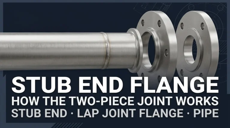
Stub end flange is a common search term, but the connection normally involves two separate piping components: a stub end and a lap joint flange.
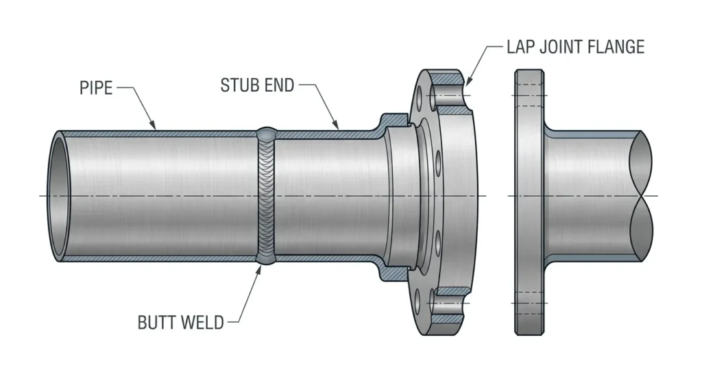
The stub end is butt-welded to the pipe and provides the lap or sealing interface. The lap joint flange remains loose behind the stub end during assembly, allowing it to rotate for bolt-hole alignment before the flange joint is tightened.
This two-piece arrangement can be useful in stainless steel and other corrosion-resistant piping systems, but the stub end, backing flange, material, dimensions, wall thickness, gasket, bolting and applicable piping code still have to be selected as one compatible joint.
This guide explains how a stub end flange connection works, the difference between the stub end and lap joint flange, which standards apply, and what engineers and buyers should include in an RFQ.
What Is a Stub End Flange?
The term stub end flange is commonly used to describe a lap-joint flanged connection that combines:
- a butt-weld stub end;
- a loose lap joint or backing flange;
- a mating flange;
- the required gasket and bolting system.
The stub end and lap joint flange are not the same component.
The straight end of the stub end is welded to the pipe. Its flared or lapped end forms the interface against which the loose flange bears when the joint is bolted.
The lap joint flange slides over the pipe and stub-end neck before final assembly. Because it is not normally welded directly to the pipe, it can rotate during alignment before the bolts are tightened.
This ability to rotate is one of the practical reasons lap-joint assemblies are used where bolt-hole alignment, maintenance or assembly flexibility is important.
Stub End vs Lap Joint Flange: Which Part Does What?
| Component | Main Function | Buyer Should Confirm |
|---|---|---|
| Stub End | Butt-welds to the pipe and provides the lapped/sealing interface | Material, NPS/DN, wall thickness, type or pattern, lap dimensions, length and weld end |
| Lap Joint Flange | Provides the loose backing and bolting interface | Size, flange standard, pressure class, material, bore, bolt pattern and compatibility with the stub end |
| Gasket | Provides the specified sealing element between mating flange surfaces | Type, material, dimensions and service compatibility |
| Bolting | Applies and maintains flange-joint clamping force | Material, size, length, specification and assembly requirements |
The key procurement point is that stub-end and flange compatibility should be checked as one interface.
Ordering the stub end and backing flange independently without confirming lap geometry, bore, dimensions and project requirements can create alignment or assembly problems.
How Does a Lap Joint Flange and Stub End Assembly Work?
The assembly sequence can be understood in four steps.
1. The Lap Joint Flange Is Positioned Behind the Stub End
The loose flange is placed over the pipe or stub-end neck before the final butt-weld arrangement prevents it from being removed.
2. The Stub End Is Butt-Welded to the Pipe
The welding end of the stub end is aligned with the connected pipe and joined using the approved welding procedure and project requirements.
The exact bevel, fit-up, welding procedure, filler material, heat control and examination requirements depend on the applicable standards and project specification.
For fabrication-document requirements, see our WPS for butt-weld pipe guide.
3. The Loose Flange Can Be Rotated for Alignment
Before final bolting, the lap joint flange can rotate behind the stub end. This can make bolt-hole alignment easier than with a flange that has already been permanently welded in a fixed orientation.
4. The Flanged Joint Is Bolted to the Mating Connection
When the joint is assembled, the backing flange transfers the bolting force through the stub-end lap and the specified gasket interface.
The final flange-joint performance depends on more than the stub end alone. Flange material and class, gasket selection, bolting, alignment, surface condition, assembly procedure and system design must all be compatible.
For the broader assembly and inspection framework used for pressure-boundary bolted flange joints, see our ASME PCC-1 guide.
Why Use a Stub End with a Lap Joint Flange?
A stub end and lap joint flange arrangement can provide several practical advantages when it is appropriate for the project.
Easier Bolt-Hole Alignment
Because the loose backing flange can rotate before final tightening, installers have more flexibility when aligning bolt holes with mating equipment or piping flanges.
Potential Material Optimization
The stub end is normally part of the process-side piping material system. The backing flange may, where permitted by the project, be selected from a different material because it does not serve the same wetted function as the stub-end face.
This can create a material-cost opportunity in some stainless steel or higher-alloy piping systems.
However, a lower-cost backing material should never be assumed automatically. External corrosion, temperature, mechanical loading, material compatibility, project standards and environmental conditions still need to be reviewed.
Maintenance and Disassembly Flexibility
A loose flange arrangement can simplify alignment and may be useful where piping equipment or components need periodic disconnection.
That does not mean every lap joint flange can be indefinitely reused. Flange condition, corrosion, distortion, bolt-hole damage and project inspection requirements should be checked before reuse.
When Is a Stub End Flange Not an Automatic Choice?
Lap-joint assemblies are useful in many applications, but they should not be treated as universally preferable to weld-neck, slip-on or other flange arrangements.
The project engineer may need to review:
- design pressure and temperature;
- external piping loads;
- vibration and cyclic loading;
- flange-joint stiffness;
- gasket and bolting requirements;
- corrosion environment;
- inspection access;
- maintenance strategy;
- applicable piping code;
- client or licensor specifications.
The correct flange arrangement is therefore a system-design decision, not simply a purchasing preference.
Stub End Types: A, B and C
Industry catalogs commonly describe stub ends using Type A, Type B and Type C terminology.
These names are generally used to distinguish differences in lap geometry, corner radius and compatibility with the intended backing flange.
| Common Industry Term | Typical Interpretation | Buyer Check |
|---|---|---|
| Type A | Commonly associated with a dedicated lap joint flange | Confirm lap radius, flange bore and applicable dimensional standard |
| Type B | Commonly associated with a compatible slip-on or backing flange arrangement | Confirm the actual flange used and the required lap geometry |
| Type C | Commonly describes a flared form used with a compatible backing flange | Confirm the approved drawing, lap dimensions and flange interface |
Do not order a stub end using only “Type A,” “Type B” or “Type C.”
Industry terminology is not always presented consistently across catalogs. The purchase order should identify the applicable dimensional standard, stub-end pattern or drawing, NPS/DN, wall thickness and matching flange requirement.
Long Pattern vs Short Pattern Stub Ends
Stub ends may also be described as long pattern or short pattern.
The distinction affects the overall length and therefore the available straight section between the lap and the butt-weld end.
Buyers should not assume that a type letter automatically defines the pattern length.
Instead, confirm:
- applicable stub-end standard;
- long or short pattern where specified;
- overall length;
- lap diameter and thickness;
- corner radius;
- NPS/DN;
- pipe Schedule or nominal wall thickness;
- weld-end geometry.
MSS SP-43 is particularly relevant to corrosion-resistant butt-weld fittings within its defined scope, including fittings for Schedule 5S and 10S pipe and specified short-pattern stub-end applications.
The controlled project edition and dimensional table should always be used for final procurement rather than a generic online dimension chart.
Which Standards Apply to a Stub End Flange Connection?
A complete stub-end and flange assembly normally relies on several technical documents rather than one standard number.
| Standard / Document | Typical Role |
|---|---|
| ASME B16.9 | Factory-made wrought butt-weld fitting dimensional requirements, including lap-joint stub ends within its scope |
| ASTM A403/A403M | Material and product requirements for wrought austenitic stainless steel piping fittings |
| ASME B16.5 | Pipe flange and flanged-fitting requirements within its applicable size and class scope |
| MSS SP-43 | Wrought and fabricated butt-weld fittings for defined low-pressure, corrosion-resistant applications |
| ASME B16.25 | Butt-welding end-preparation requirements where applicable |
| Applicable Piping Code | System design, fabrication, examination, testing and service requirements |
| Project Specification | Final material, class, gasket, bolting, inspection, documentation and approval requirements |
Our ASME B16.9 butt-weld fittings guide explains why a dimensional standard does not replace the material specification or complete project requirements.
For stainless steel fitting material requirements, see our ASTM A403 fittings guide.
ASTM A403 Stainless Steel Stub Ends
For wrought austenitic stainless steel pressure-piping fittings, ASTM A403/A403M may be specified together with the applicable dimensional standard.
A complete stainless steel stub-end description therefore needs more than the words “316 stub end.”
The purchaser may need to identify:
- ASTM material/product specification;
- grade, such as the project-required WP304L or WP316L designation;
- manufacturing class where applicable;
- NPS or DN;
- Schedule or nominal wall thickness;
- stub-end dimensional standard;
- pattern or approved drawing;
- weld-end preparation;
- inspection requirements;
- material test documentation.
ASTM A403 and ASME B16.9 perform different roles. One should not be substituted for the other when both are required.
Does a Stub End Have a Pressure Class?
A stub end should not be specified as though it independently carries the same flange Class designation as the loose backing flange.
For example, Class 150 or Class 300 terminology belongs to the applicable flange-rating system and does not by itself define the stub-end material, wall thickness or complete assembly pressure capability.
The suitability of the assembled joint depends on the complete design, including:
- stub-end material and wall thickness;
- lap geometry;
- backing flange standard, material and class;
- gasket;
- bolting;
- design temperature;
- corrosion allowance;
- external loads;
- applicable piping code and project requirements.
Similarly, pipe Schedule is a wall-thickness designation and should not be treated as a universal pressure rating.
If you need to confirm NPS, outside diameter and Schedule terminology first, review our stainless steel pipe dimensions guide.
Stub End Material vs Backing Flange Material
One reason stub-end assemblies are considered for stainless steel and higher-alloy systems is that the two components perform different functions.
The stub end forms part of the process-side piping connection and should satisfy the project’s material and corrosion requirements.
The loose backing flange does not perform the same wetted function, so some project specifications may permit a different flange material.
However, the choice must still consider:
- external corrosion;
- dissimilar-metal contact;
- temperature;
- mechanical properties;
- bolting compatibility;
- coating requirements;
- project material restrictions.
Therefore, “stainless stub end + carbon steel backing flange” should be treated as a project-specific option, not a universal rule.
How to Select a Stub End and Lap Joint Flange
A practical selection sequence is:
| Step | Selection Question |
|---|---|
| 1. Pipe | What material, NPS/DN and wall thickness or Schedule are specified? |
| 2. Stub End Material | Which ASTM or other product/material specification and grade apply? |
| 3. Stub End Geometry | Which standard, pattern, type and lap dimensions are required? |
| 4. Backing Flange | Which flange standard, material, class and bore are required? |
| 5. Interface | Are the stub-end lap radius and backing-flange geometry compatible? |
| 6. Gasket and Bolting | What gasket, bolting and assembly requirements apply? |
| 7. Welding | What butt-weld end preparation and WPS requirements apply? |
| 8. Service | What pressure, temperature, medium, corrosion and external loads apply? |
| 9. Documentation | What MTR, drawings, dimensional reports, NDE and inspection records are required? |
This selection process prevents one of the most common purchasing problems: ordering a correct nominal-size stub end that does not properly match the intended backing flange or project piping specification.
Need Help Matching a Stub End to Your Piping Specification?
Nonleak can help review whether the basic product and RFQ information is complete before quotation.
Send the pipe size, wall thickness, stainless steel grade, stub-end standard or drawing, matching flange requirement and required project documentation.
What to Include in a Stub End Flange RFQ
| RFQ Item | Information to Provide |
|---|---|
| Component | Stub end, backing flange, or complete assembly scope |
| Stub End Standard | ASME B16.9, MSS SP-43 or project-required standard/drawing |
| Material Specification | ASTM A403/A403M or other applicable product specification |
| Material Grade | Exact project-required grade |
| Size | NPS / DN |
| Wall | Schedule or nominal wall thickness |
| Pattern / Type | Required type, long/short pattern or approved drawing reference |
| Backing Flange | Standard, material, size and pressure class |
| Weld End | Standard or project-specific end preparation |
| Gasket / Bolting | Where included in the supply scope, state required specifications |
| Inspection | Required dimensional checks, PMI, NDE or third-party inspection |
| Documentation | MTR, drawings, inspection reports and traceability requirements |
| Quantity | Number of pieces for each size, wall and material |
Example RFQ Description
An illustrative stainless steel stub-end request might be written as:
Stub End:
ASTM A403/A403M WP316L, ASME B16.9 lap-joint stub end, NPS 4, Schedule 10S, butt-weld end, with project-required material certificate and inspection documentation.
Matching Backing Flange:
ASME B16.5 lap joint flange, NPS 4, project-required pressure class and material, compatible with the specified stub end and flange-joint requirements.
This example demonstrates RFQ structure only. It is not a recommended size, material, pressure class or service condition. The final specification must follow the approved project documents and applicable standard editions.
Common Stub End Flange Specification Mistakes
1. Treating the Stub End and Flange as One Component
The stub end and loose backing flange have different functions and may be governed by different product requirements.
2. Ordering Only by NPS
Nominal size does not define the wall thickness, lap dimensions, overall length or backing-flange geometry.
3. Assuming Type A Means Long Pattern
Type terminology and pattern length describe different aspects of the product. Confirm the actual standard and drawing rather than relying on shorthand.
4. Forgetting Pipe Wall Thickness
The stub-end weld end must be compatible with the connected pipe. State the Schedule or actual nominal wall thickness.
5. Selecting the Backing Flange Separately
The flange bore and interface geometry need to accommodate the selected stub end.
6. Treating Flange Class as the Complete Pressure Rating
Flange class alone does not define the allowable conditions of the complete piping assembly.
7. Assuming the Backing Flange Can Always Use a Cheaper Material
A different backing-flange material may be possible in some projects, but corrosion, temperature, mechanical and project requirements still apply.
Stub End Flange FAQ
What is a stub end flange?
“Stub end flange” commonly refers to a two-piece lap-joint connection using a stub end and a loose lap joint flange. The stub end is butt-welded to the pipe, while the loose flange provides the bolting interface.
Is a stub end the same as a lap joint flange?
No. The stub end is the fitting welded to the pipe. The lap joint flange is the loose backing component positioned behind the stub-end lap.
Why does a lap joint flange rotate?
Because it is not normally welded directly to the pipe, the backing flange can rotate during assembly before the flange joint is tightened. This helps with bolt-hole alignment.
Is a stub end covered by ASME B16.9?
ASME B16.9 includes dimensional requirements for lap-joint stub ends within its scope. The material specification, wall thickness, flange, welding and project requirements still need to be identified separately.
What is MSS SP-43 used for?
MSS SP-43 covers wrought and fabricated butt-welding fittings for defined low-pressure, corrosion-resistant applications. Its current scope includes fittings associated with Schedule 5S and 10S piping and specified short-pattern stub-end applications.
Can a stainless steel stub end use a carbon steel backing flange?
It may be permitted in some projects because the backing flange performs a different function from the wetted stub end. However, material compatibility, external corrosion, temperature, loads, coating and project requirements must be reviewed before making that selection.
Does a stub end have a Class 150 or Class 300 rating?
Do not treat the stub end alone as though it carries the complete flange Class rating. The backing flange, stub end, pipe wall, gasket, bolting, material, temperature and governing piping code must be evaluated as a complete joint.
What information is needed when ordering a stainless steel stub end?
Provide the applicable standard, material specification and grade, NPS or DN, Schedule or wall thickness, required type or pattern, matching flange requirement, end preparation, inspection, documentation and quantity.
Stainless Steel Stub Ends for Butt-Weld Piping Projects
Nonleak supplies stainless steel stub ends as part of its butt-weld fittings range.
For product-specific availability, dimensions and quotation requirements, review our stainless steel butt-weld stub end product page.
Preparing a Stub End or Butt-Weld Fitting RFQ?
Send the required material grade, size, wall thickness, stub-end standard or drawing, matching flange requirement, quantity and project documentation requirements.
Technical Note: This article is a general selection and procurement guide. It does not reproduce or replace the controlled text of ASME, ASTM, MSS, the governing piping code, approved engineering calculations or project specifications. Always confirm the required standard edition and approved project documents before ordering.