A hydrostatic pressure test is used to check whether a completed piping system can hold a specified liquid pressure without visible leakage, unacceptable pressure loss or permanent deformation. Because water is far less compressible than air, hydrostatic testing generally stores less energy than pneumatic testing at the same pressure. However, it still requires a controlled test package, calibrated instruments, suitable isolation and a safe exclusion area.
This guide explains how hydrostatic pressure testing is typically prepared, performed, inspected and documented for piping systems. It also highlights issues that are especially relevant to stainless steel pipe and press-fit installations. The approved project specification, governing piping code, manufacturer instructions and local safety requirements always take precedence over this general guide.
Quick answer: A hydrostatic pressure test normally involves reviewing the test package, isolating the test section, filling it with a suitable liquid, removing trapped air, increasing pressure in controlled stages, allowing the system to stabilize, inspecting joints and components, holding the required pressure, recording the results, depressurizing safely, draining and restoring the line. The required test pressure and holding time must come from the governing code and project documents rather than a universal rule.
What Is a Hydrostatic Pressure Test?
Hydrostatic testing is a liquid-pressure test performed on pipe, fittings, joints, valves and other components within an approved test boundary. Water is the most common test medium, although another compatible liquid may be specified when water could damage the system, contaminate the process or create a freezing risk.
The test is intended to provide evidence that the assembled piping section has adequate pressure integrity under the specified test conditions. It may help identify:
- leaking mechanical or press-fit joints;
- defective welds or threaded connections;
- damaged gaskets, seals or valve packing;
- loose closures, plugs or temporary connections;
- incorrectly installed fittings or components;
- unacceptable movement, distortion or support problems.
A successful test does not prove that the system is suitable for every operating condition. Material compatibility, corrosion resistance, fatigue, temperature, water quality, flow conditions and long-term maintenance still require separate engineering review.
Hydrostatic Testing vs Pneumatic and Air-Tightness Testing
Hydrostatic, pneumatic and air-tightness tests are related but not interchangeable. The test medium, stored energy, objective, procedure and acceptance criteria can differ significantly.
| Test type | Typical medium | Primary purpose | Key consideration |
|---|---|---|---|
| Hydrostatic pressure test | Water or another compatible liquid | Verify pressure integrity under a specified liquid pressure | Air must be removed, and the system must be drained and dried as required |
| Pneumatic pressure test | Air or inert gas | Verify pressure integrity where liquid testing is impractical or prohibited | Compressed gas stores much more energy and requires stricter safety controls |
| Air-tightness or leak test | Air, nitrogen, tracer gas or another approved medium | Detect leakage at a defined test pressure or sensitivity | May be performed at a different pressure and under a different procedure from a strength test |
Where pneumatic testing is proposed, the decision should be made by qualified personnel under the applicable code and safety procedure. It should not be used merely because it is faster or avoids draining the system.
Define the Test Boundary Before Pressurization
The first step is to identify exactly which part of the system will be tested. The test package should define the start and end points, included components, excluded equipment, design documents, required pressure, holding period, test medium and acceptance criteria.
Before filling the line, confirm:
- the piping installation is complete for the approved test scope;
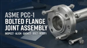
- all required welds, press-fit joints, threaded joints and flanges are finished;
- temporary blanks, caps and plugs are rated and secured;
- equipment that must not receive the test pressure has been isolated or removed;
- relief devices, instruments and control valves are treated according to the test plan;
- high-point vents and low-point drains are available;
- supports can carry the added weight of the test liquid;
- the test section can expand or move without creating harmful loads;
- all open ends and temporary hoses are restrained;
- the exclusion area and communication method are established.
Water is heavy. A long pipe run that is acceptable when empty may impose much larger loads on hangers, branches and temporary supports when filled. Support review is therefore part of test preparation, not an optional housekeeping task.
Prepare Stainless Steel Pipe and Press-Fit Joints
For stainless steel piping, the test medium and post-test condition deserve particular attention. Water chemistry, chloride content, cleanliness, temperature and the time water remains trapped in the line can affect corrosion risk. The required water quality should come from the project specification or approved test procedure rather than a general numerical limit copied from another project.
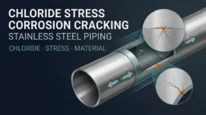
For stainless steel systems, chloride-bearing residual water is not only a localized-corrosion concern; under the wrong combination of environment and tensile stress it can also contribute to chloride stress corrosion cracking risk.
Good preparation may include:
- using clean, compatible test water;
- preventing contamination from carbon-steel tools, debris or temporary fittings;
- removing foreign material before filling;
- planning complete drainage from low points;
- drying or preserving the line after testing when required;
- avoiding prolonged stagnant water retention.
For press-fit piping systems, verify that every joint is fully assembled and pressed with the approved tool, jaw or ring for that fitting system. Check insertion-depth marks, alignment, pipe-end preparation, seal condition and visible press indications before the line is covered or insulated.
Some fitting systems are designed to show leakage when left unpressed, but this feature is not universal and should never replace visual inspection or manufacturer instructions.
Hydrostatic Pressure Test Equipment
The test setup should be selected for the pressure range, system volume and required accuracy. A typical arrangement may include:
- a clean water source and filling connection;
- a hydrostatic test pump suitable for controlled pressurization;
- one or more calibrated pressure gauges;
- a pressure relief or controlled overpressure device;
- high-point vents and low-point drains;
- rated hoses, connectors, manifolds and temporary closures;
- temperature measurement when required;
- barriers, warning signs and communication equipment;
- a test record or digital data-logging system.
The pressure gauge range should allow the required test pressure to be read clearly. Its calibration status and identification should be recorded. Where the system is large, elevated or complex, more than one gauge may be needed to account for pressure differences caused by elevation and to confirm pressure at critical locations.
Hydrostatic Pressure Test Procedure
1. Review the approved test package
Confirm the latest drawings, line list, test boundary, test pressure, test medium, holding time, acceptance criteria and required signatures. Resolve discrepancies before filling the line.
2. Inspect the installed piping
Check that fabrication and installation are complete within the test boundary. Verify joint completion, supports, anchors, guides, temporary closures, valve positions and equipment isolation.
3. Fill from a low point
Introduce the test liquid gradually from a low point while opening high-point vents. Slow filling helps displace air and reduces the chance of trapping compressible pockets.
4. Remove trapped air
Keep vents open until a steady liquid flow is observed. Trapped air can create misleading pressure behavior and increase stored energy. Complex branches, high loops and dead legs may require additional venting.
5. Check for obvious leaks at low pressure
Before approaching the formal test pressure, inspect temporary connections, closures and accessible joints at a lower pressure. Correct visible problems only after the section has been safely depressurized.
6. Increase pressure in controlled stages
Raise pressure gradually according to the approved procedure. Pause at specified stages when required to check stability, movement and leakage. Do not stand in front of temporary blanks, caps, plugs or other potential release paths.
7. Allow the system to stabilize
Pressure may change as the pipe expands slightly, trapped air dissolves, water temperature changes or temporary hoses settle. Follow the approved stabilization method before beginning the formal holding period.
8. Inspect at the required test pressure
Examine accessible welds, press-fit joints, threaded joints, flanges, valves, closures and branch connections. Look for visible leakage, sweating, abnormal movement, deformation or pressure behavior outside the acceptance criteria.
9. Hold and record the test
Maintain the pressure for the period required by the governing code and project specification. Record start and finish times, pressure readings, temperature where required, gauge identification, test medium, observations and personnel involved.
10. Depressurize gradually
Release pressure through a controlled route. Confirm zero pressure before loosening any closure, connection or component. Do not rely solely on one gauge indication if isolation or blockage is possible.
11. Drain, dry and reinstate the system
Drain the liquid from all low points, dry or preserve the piping as required, remove temporary test items and reinstall excluded equipment. Complete the reinstatement checklist before the system is released for the next construction or commissioning stage.
How Is a Hydrostatic Pressure Test Accepted?
Acceptance criteria must be stated in the approved test procedure. Depending on the project, acceptance may require:
- no visible leakage from pressure-containing joints or components;
- no unacceptable permanent deformation or movement;
- pressure behavior within the permitted limits;
- completion of the specified holding period;
- confirmation that all test instruments were valid and calibrated;
- completion of inspection and witness signatures;
- successful drainage, drying and reinstatement.
A pressure decrease does not automatically prove a leak. Temperature change, elevation, system expansion, trapped air and test-equipment behavior can affect readings. However, unexplained pressure loss must be investigated rather than simply corrected by repeatedly pumping the system back to the target pressure.
Common Hydrostatic Testing Mistakes
| Common mistake | Possible consequence | Better practice |
|---|---|---|
| Using an assumed test pressure | Overstressing components or performing an invalid test | Use the approved code calculation and project test package |
| Failing to remove trapped air | Unstable readings and increased stored energy | Fill slowly and vent all high points |
| Ignoring the weight of test water | Excessive loads on supports, branches or temporary structures | Review support capacity before filling |
| Pressurizing excluded equipment | Damage to instruments, valves or connected equipment | Verify isolation against the approved boundary drawing |
| Using uncalibrated gauges | Unreliable pressure records and rejected documentation | Record gauge range, serial number and calibration status |
| Leaving water in stainless steel piping | Contamination, staining or corrosion risk under unsuitable conditions | Drain and dry according to the project procedure |
| Repairing a live test section | Serious injury from stored pressure or component release | Depressurize, verify zero energy and then repair |
Hydrostatic Test Records and Documentation
A clear test record supports project acceptance and future traceability. The report commonly includes:
- project and system identification;
- test package or line number;
- drawing and revision references;
- test medium and water-quality requirements;
- required and actual test pressure;
- start time, finish time and holding period;
- ambient and fluid temperature when required;
- pressure gauge identification and calibration status;
- inspection observations and repairs;
- witness, contractor and owner signatures;
- drainage, drying and reinstatement confirmation.
Photographs can support the record, but they should show the correct test setup and be linked to the relevant test package. A photograph alone is not a substitute for calibrated readings and signed documentation.
Frequently Asked Questions
What pressure should be used for a hydrostatic pressure test?
The test pressure must be determined from the governing piping code, design conditions, component ratings and project specification. There is no single multiplier or pressure value that is correct for every piping system.
How long should a hydrostatic pressure test be held?
The required holding time depends on the applicable code, system type, project procedure and inspection needs. Use the approved test package rather than a generic duration copied from another installation.
Why must air be removed before hydrostatic testing?
Trapped air is compressible. It can cause unstable readings, increase stored energy and make pressure behavior harder to interpret.
Can a hydrostatic test be performed on press-fit piping?
Yes, when the pipe, fittings and system design permit it. All joints must be assembled and pressed according to the fitting manufacturer’s instructions, and the test must follow the approved project procedure.
Is air testing the same as a hydrostatic pressure test?
No. Hydrostatic testing uses a liquid, while pneumatic or air-tightness testing uses a gas. The safety controls, stored energy and acceptance criteria can be different.
Does zero visible leakage always mean the test passed?
Not necessarily. The system must also satisfy the required pressure behavior, holding time, deformation limits, documentation and other acceptance criteria.
What should be done after testing stainless steel piping?
Drain the system completely and dry, flush or preserve it as required by the project specification. Avoid leaving unsuitable stagnant test water in the piping.
Can a leaking press-fit joint simply be pressed again?
Do not repressurize or repair a live system. After safe depressurization, follow the fitting manufacturer’s instructions and project procedure. Depending on the cause and system design, replacement may be required rather than repeated pressing.
Plan Testing Before the Piping Is Covered
Hydrostatic testing is most effective when inspection access, vents, drains, isolation points and documentation are planned before the piping is concealed or insulated. Early coordination reduces rework and makes it easier to confirm every joint within the test boundary.
Nonleak provides stainless steel pipes, pipe fittings and technical support for commercial and industrial piping projects. Review our testing and acceptance guidance, technical documentation, quality control process, stainless steel pipes and stainless steel pipe fittings. For project-specific supply requirements, send the applicable standard, system type, size range, pressure conditions and inspection documents through our contact page.
Technical note: This article provides general information only. Hydrostatic and pneumatic tests must be planned and supervised by qualified personnel in accordance with the governing code, approved test procedure, manufacturer instructions and local safety requirements.